The BeamWise team contributed an article to the May 2017 issue of Laser Focus World that highlighted the coherent workflow for optical system design provided by BeamWise.
BeamWise® Optical System Design Workflow Profiled in Laser Focus World
What follows are some excerpts from a recent article by the BeamWise team entitled “Optical System Design: Software environment creates coherent workflow for optical system design” that appeared in the May 2017 issue of Laser Focus World.
Optical System Design Feels Like The Stepchild of the Digital Revolution
“Optical system design feels like the stepchild of the digital revolution. While powerful, intuitive, fast computer-based tools are available to engineers in fields from integrated-circuit layout to aircraft design and architecture, designers of optical systems are coping, for the most part, with antiquated software. Optical systems have numerous complex constraints and requirements—their challenges go beyond designing the perfect lens or excellent components.”
from “Optical System Design: Software environment creates coherent workflow for optical system design“
Optical system design remains an “analog design” problem for the most part. Using an optical bench based prototype to assess performance remains the commonly accepted approach.
BeamWise Interface Model
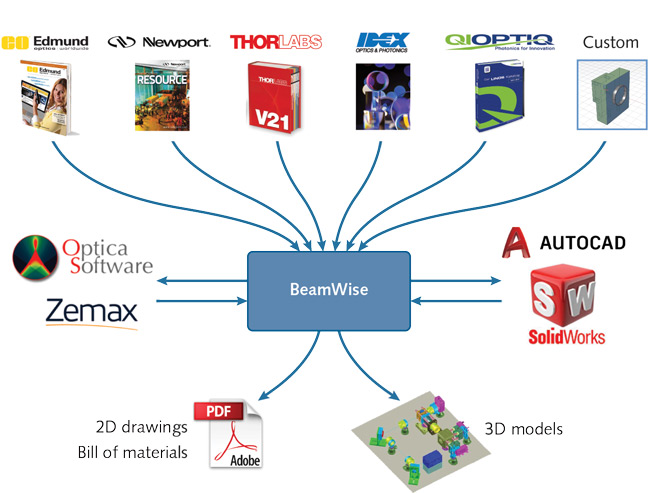
BeamWise does not replace CAD systems or detailed optical modeling tools—rather, it integrates these tools into a coherent workflow for optical system design (see Fig. 1). Each tool thus can perform efficiently at what it does best for the benefit of the entire design process. The BeamWise 3D Model, a “virtual optical bench,” can be seamlessly imported into CAD environments. Because it allows bidirectional interfacing with the other tools, designers can have real-time visualization, interactive change management, instant addressing of physical conflicts, efficient design reuse, and transparent capture of design intent.
from “Optical System Design: Software environment creates coherent workflow for optical system design“
The BeamWise team has been at work on this approach since 2013, our goal is to integrate existing approaches and replace whiteboard / paper sketches and a certain amount of tinkering on the optical bench.
BeamWise Workflow
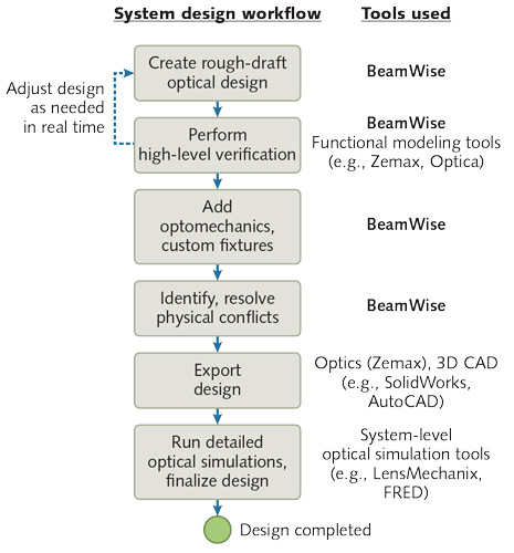
A step-by-step design workflow is shown for a complex optical system. It is more efficient to iterate at a high level first, and refine later. With BeamWise, designers create a rough design layout, verify the design in real time, implement optomechanical supports, and export to specialized tools for final checks.

- Rough out a design. Create a virtual optical bench in real time in the BeamWise environment. The system concept–the equivalent of a hand-drawn sketch–is translated into a functional layout of optical components.
- Perform high-level verification(optional). Through bidirectional interfaces built into BeamWise, send the optical system prescription to simulation and optical modeling software such as Zemax OpticStudio or Optica. By focusing only on the essential elements, this stage can verify in real time that the design architecture is sound.
- Iterate. Automatically import any modifications back into BeamWise and repeat the verification process as needed.
- Add optomechanical fixturing. Use off-the-shelf components from catalogs such as those from Thorlabs, Newport, Edmund, and Qioptiq to support and integrate all the optical components, or incorporate custom parts from proprietary design files.
- Analyze physical conflicts. Use BeamWise to identify and resolve any issues caused by mounting.
- Export the system to design tools. Transmit the resulting complete system (optics and optomechanics) as a 3D file to CAD tools such as SolidWorks or AutoCAD for mechanical and manufacturing engineers to use. BeamWise can also generate 2D engineering drawings and bills of materials.
- Analyze optical performance (optional). As the final step, export the results to optical analysis software such as LensMechanix, Code V, or FRED to run detailed simulations and perform stray-light analysis. Note that these simulations take a long time and cannot be iterated quickly.
Advantages of an integrated Approach
“As a system design tool, the software allows designers to visualize the entire optical and mechanical system before committing to specific hardware, cutting metal, or buying parts. This reduces redesign and rework, and eliminates the inconvenience and expense of parts returns and scrapping. The software provides an intelligent link to the optical layer, allowing bidirectional transfer of information to specialized optical modeling tools. Designers can take advantage of the capabilities of these tools knowing that no information has fallen through the cracks.
This approach also enables designers to reuse and recycle existing designs. Because components are anchored to the local optical axis, altering the baseline design to generate a derivative system is much faster than starting from scratch. The revised model still incorporates the intelligent optical path definitions used for bidirectional interfacing to specialized modeling tools.”
from “Optical System Design: Software environment creates coherent workflow for optical system design“
Our primary goal from the beginning was to replace hand drawn representations of the design with intelligent drawings that enable the creation of reusable templates and the intelligent adjustment of sections of a beam path. To this end relationships have been defined relative to the beam not from a single origin point for the system. We continue to refine our approach and are currently at work on some significant improvements for 2018, please contact us if you would like to get an demonstration or arrange for an evaluation.
